In this post we will touch different topics, although they are all going to be related to Internet Protocol concepts. What is ICMP anyways ? what are the different IPv4 options ? what is fragmentation ? how does the IP MTU and TTL relate to ICMP messages ? these are all questions that we will try to address in this post. Sit back and enjoy.
Internet Protocol
Let’s very briefly review the composition of an IP packet and after that we will be able to discuss some of the Options and functionalities. IP is explained in RFC-791.
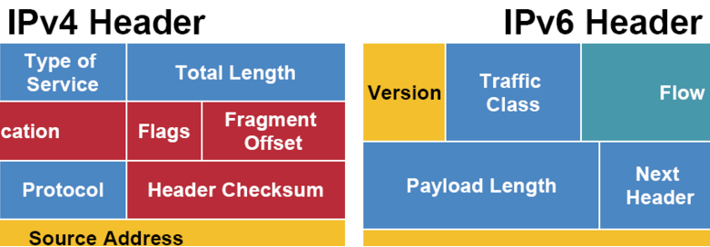
Simply put, IP is a protocol that allows to move datagrams from one node to another, all IP datagrams will be at least 20 bytes in size (assuming no data) because of the standard header which contains information such as source and destination address, TTL, etc, after this 20 byte standard header, we need to add the extra bytes for the actual data included in the IP packet. So we will end up having a very common IP header with very well known fields such as the source and destination address, the TTL field, Version, etc. The following is the composition of the IP header, let’s examine some of the most important fields.

Version is 4 bits in size, just enough to write 0100 for Version 4 (IPv4).
Internet Header Length (IHL) is 4 bits in size and reflects the length of the IP header (not the data) in 32 bit words, further down we will see how the Options header can vary in size, and so the IHL has a minimum size of 5 words, meaning (32 bits) x 5 = 160 bits or the same as 20 bytes, like mentioned before.
Type of Service (ToS) is 8 bits in size and allows us to set the precedence (0~2 bits) for the packet, and manipulate the delay/throughput/reliability (3~5 bits) and leaves the bits 6 and 7 as reserved.
Total Length is 13 bits in size and is measured in octects, this field defines the complete size of the datagram (IP standard header + Data).
Flags is 3 bits in size, bit 0 is always going to be 0, bit 1 is used to specify whether we want to enable fragmentation or not, bit 2 is used to tell the receiver whether this fragment is the last fragment of the original datagram or if more fragments are coming.
Time To Live (TTL) is 8 bits in size and basically is a field that controls how many hops a datagram is going to be able to take before it dies. TTL is used for the traceroute tool, datagrams get sent with TTL increments of 1 at a time starting from 1, that makes each next node send an ICMP time exceeded (type 11) to the source or traceroute initiator.
Header Checksum is 16 bits in size and only takes into account the header fields as the name indicates, the reason for this field is because the IP header changes in every hop the datagram takes, so we will constantly check for integrity.
Source/Dest Address are 32 bits each and as we already know these contain the source and destination IPv4 address in 4 octets format.
Now that we are more familiar with the basic components of an IPv4 header, let’s take a look at the last field called Options, which complements with the Padding one, there’s a good explanation on how the Options field works on RFC-791, this is a brief overview:
The Options field can contain one or multiple options, and each option can be 1 byte or multiple bytes long, hence why its said that the Options field can vary in length, but remember the IP header size has to be in multiples of 32 bits, and that’s why we have the Padding field, to make up for whatever rest the header needs in order to reach a multiple of 32 bits (or 4 bytes).
The format of an Option can be one of these two;
Single octect for “option-type”.
An “option-type” octect, an “option-legth” octect, the “option-data” octect(s). The “option-length” octect counting the other two and itself.
Now, the option-type octect breaks out like this:
1 bit for “flag”, which indicates whether this option is copied into all fragments on fragmentation or not.
2 bits for “class”, which ranges from 0 ~ 3, 0 being control and 2 being debugging and measurement, the other 2 are “reserved”.
And then finally the “Number” which is the number that identifies the actual Option.
Here’s how it looks

And here’s the list of actual Options defined in RFC-791:

We can create an ACL to block IP packets containing certain Options, like this:
|
0 1 2 3 4 5 6 7 8 9 10 11 12 13 14 15 16 17 18 19 20 21 22 23 24 25 26 27 28 |
R1(config)#ip access-list extended list-name R1(config-ext-nacl)#deny ip any any option ? <0-255> IP Options value add-ext Match packets with Address Extension Option (147) any-options Match packets with ANY Option com-security Match packets with Commercial Security Option (134) dps Match packets with Dynamic Packet State Option (151) encode Match packets with Encode Option (15) eool Match packets with End of Options (0) ext-ip Match packets with Extended IP Option (145) ext-security Match packets with Extended Security Option (133) finn Match packets with Experimental Flow Control Option (205) imitd Match packets with IMI Traffic Desriptor Option (144) lsr Match packets with Loose Source Route Option (131) mtup Match packets with MTU Probe Option (11) mtur Match packets with MTU Reply Option (12) no-op Match packets with No Operation Option (1) nsapa Match packets with NSAP Addresses Option (150) record-route Match packets with Record Route Option (7) router-alert Match packets with Router Alert Option (148) sdb Match packets with Selective Directed Broadcast Option (149) security Match packets with Basic Security Option (130) ssr Match packets with Strict Source Routing Option (137) stream-id Match packets with Stream ID Option (136) timestamp Match packets with Time Stamp Option (68) traceroute Match packets with Trace Route Option (82) ump Match packets with Upstream Multicast Packet Option (152) visa Match packets with Experimental Access Control Option (142) zsu Match packets with Experimental Measurement Option (10) |
If interested in learning more about how to implement IPv4 Options, this is the only draft that I could find.
Internet Control Message Protocol
So ICMP is something that we tend to take for granted, we use it every day to ping our devices, to trace our networks via traceroute, to get valuable information regarding hosts and nodes. But how does it work and whats it comprised of ? ICMP is explained in RFC-792.
ICMP is the protocol number 1, and it is the control protocol for the IP, meaning it will allow us to carry control information about the the sending and receiving of datagrams, for example, if a host1 tries to send a datagram to another host2, but this host2 turns out not to be there anymore, how is host1 going to know that ? What if the gateway doesn’t have the buffering capacity to send a datagram ? Or maybe the gateway finds that there’s a better gateway for the sender and wants to communicate that to him. These are all applications for ICMP.
Now, ICMP uses the same basic IP header, and the first octect of the Data field contains an ICMP “type” field, which determines the format of the remaining data. Although we will only be talking about Unreachable and Redirect messages, here’s a list of all the different types of ICMP messages.
ICMP Redirects
This is a pretty straightforward type of ICMP message, Redirect (type 5) messages will serve to let the sender of an IP packet know that there is a more optimal way for it to send the packet. Consider the following:

In this example, P1 is going to try to communicate to with P2, but P1 has R2 set as his gateway, now when R2 gets this packet, he is going to compare its main routing table against the destination address and is going to find that in order to get to P2, he needs to forward the packet out the same interface it came in, this is one of the conditions that have to be met for an ICMP redirect packet to be sent out, let’s take a look at all the conditions that R2 has to meet to be able to send the ICMP Redirect to P1:
Interface on which the packet comes in (Fa0/0), is the same on which the packet gets routed out (Fa0/0).
The subnet of the source IP address (P1) is on the same subnet of the next-hop (R1) the router would utilize.
The datagram is not source-routed (no IP Option 3 or 9 was specified for this packet).
The kernel is configured to send redirects, this is enabled by default on Cisco routers but we can use global config command to disable this per host or subnet:
|
0 1 2 |
R1(config)#ip icmp redirect ? host Send ICMP host redirects; same as 'no ip icmp redirect subnet' subnet Send ICMP subnet redirects; same as 'no ip icmp redirect host' |
We can turn on #debug ip icmp on R2 and also we’ll do a capture on Fa0/0 so we can see this better:
Monitoring the R3’s console we can see the debug message saying that an ICMP Redirect message was sent to P1 (10.0.0.1) telling him to use 10.0.0.4 as the default gateway instead for whenever he needs to send packets to 10.0.45.5.
|
0 1 |
R3# *Jun 15 23:21:58.339: ICMP: redirect sent to 10.0.0.1 for dest 10.0.45.5, use gw 10.0.0.4 |
And looking at the capture on R3’s Fa0/0 we see the echo request (ping) coming in and the ICMP redirect message going out, destined to P1, and we can see that this is a Type 5 message.

ICMP Unreachables and Time Exceeded
Ok so the reason that I’m putting these two together is because we will create an example that involves both type of ICMP messages, more specifically we will look at the key steps in a traceroute process. First let’s go over some basic definitions.
Destination Unreachable messages are considered ICMP Type 3 messages, also because we can have different flavors of unreachable destinations, we use “Codes” to distinguish them.
Type 3 messages are sent when a message cannot be delivered completely to the destination host. Six codes have been defined in RFC-792 :
Code 0: Network unreachable (commonly when wrongly subnetting)
Code 1: Host unreachable (commonly when stating bad destination address)
Code 2: Protocol unreachable (receiver doesn’t support high level application)
Code 3: Port unreachable (no port available at receiver)
Code 4: Fragmentation needed and DF (don’t fragment) bit set
Code 5: Source route failed (IP Option 9)
Seven other codes have been defines in RFC-1122
So by looking at the codes names we can conclude that codes 0, 1, 4 and 5 message types must be sent by a router or gateway device, because it would be telling us that the network or host is unreachable, meaning its not finding them. Instead codes 2 and 3 are more likely to be sent by a host, because a host can receive an ICMP query and may not find a right higher level protocol or available port for the request.
So it is safe to say that two main reasons exist for us to see Unreachable messages, the source host has specified a nonexistent address, or, the router does not have a route to the destination.
Traceroute and TTL
Time Exceeded ICMP Messages (Type 11) will be sent everytime the Time to Live field in the IP header reaches 0, and we now everytime a frame gets stripped off and the IP header is read by a router, it will decrement the TTL value by 1.
The way traceroute works is by having a sourcing host send UDP queries to a destination at randomly generated unreachable ports, and it does this incrementing the TTL on the packets by 1 a time. So what will happen is that on the first layer 3 hop, the router is going to strip off the layer 2 encapsulation, read the IP packet and decrement the TTL value by 1, because the first packet sent by the source has TTL 1, the router will generate an ICMP Time Exceeded message and send it back to the source. So next the the source host will send the same exact packet but with a TTL of 2 this time, and now it is the second hop the one that will send the ICMP Time Exceeded message. This will keep happening until we reach the actual destination of the UDP query, when it arrives at the destination the receiver host will try to respond on the solicited port, only to find that the port is not available, and will answer with a Destination Unreachable ICMP message, more specifically code 3 (port unreachable).
Let’s refer to our previous topology and do a traceroute from R1 all the way to R5 and see what happens, we will do a capture on R2’s Fa1/0 and R5’s Fa0/0.
|
0 1 2 3 4 5 6 |
R1(config)#do traceroute 10.0.45.5 Type escape sequence to abort. Tracing the route to 10.0.45.5 VRF info: (vrf in name/id, vrf out name/id) 1 10.0.12.2 12 msec 8 msec 12 msec 2 10.0.0.4 32 msec 28 msec 32 msec 3 10.0.45.5 44 msec * 32 msec |
Looking at R2’s Fa1/0 we can first see the UDP message with a TTL of 1 arriving at the interface, and then right after the ICMP TTL exceeded message being sent back to R1.

Then looking at R5’s Fa0/0 we can see the UDP message arriving and this time because the IP header says that R5 (10.0.45.5) is the destination, R5 will try to send this to the destination port (33440) only to find that the port is unavailable, and will send an ICMP Destination Unreachable (Type 3) saying the Port is Unreachable (Code 3) to the source, which is R1.

Let’s look one more time at the output of the traceroute command, on R1:
|
0 1 2 3 4 5 6 |
R1(config)#do traceroute 10.0.45.5 Type escape sequence to abort. Tracing the route to 10.0.45.5 VRF info: (vrf in name/id, vrf out name/id) 1 10.0.12.2 12 msec 8 msec 12 msec 2 10.0.0.4 32 msec 28 msec 32 msec 3 10.0.45.5 44 msec * 32 msec |
Note that R2 and R4 both responded 3 times, but R5 only responded to the first and the last UDP message, this is because of the ICMP rate-limit default behavior on Cisco routers, by default the router will rate-limit the ICMP Unreachable Messages to 1 every 500 ms.
We can see that it just happened once on R5:
|
0 1 2 3 4 5 6 7 |
R5#show ip icmp rate-limit DF bit unreachables All other unreachables Interval (millisecond) 500 500 Interface # DF bit unreachables # All other unreachables --------- --------------------- ------------------------ FastEthernet0/0 0 1 |
And we can also turn that off if we want to, which should only be for informational purposes because this is a built-in security for the router.
|
0 1 |
R5(config)#no ip icmp rate-limit ? unreachable ICMP type 3, Destination Unreachable |
Path MTU Discovery
As you may already know the IP MTU or Maximum Transmission Unit is the size in bytes of an IP packet that the interface is going to allow before start fragmenting the packet into smaller pieces, this is something we generally want to avoid since excessive fragmentation can lead to issues. On regular business Cisco router default MTU is 1500 bytes.
We will consider PMTUD to review IP MTU and fragmentation, let’s consider one more time our previous topology. We will set R4’s Fa3/0 interface IP MTU to 1200 bytes instead of the default 1500 bytes, and then we will ping R5 from R1 with a 1500 bytes packet, but we will set the DF bit to 1:
|
0 1 2 3 4 5 6 7 8 9 |
R4(config)#int fa3/0 R4(config-if)#ip mtu 1200 R4(config-if)#exit R1#ping 10.0.45.5 df-bit size 1500 Type escape sequence to abort. Sending 5, 1500-byte ICMP Echos to 10.0.45.5, timeout is 2 seconds: Packet sent with the DF bit set .... Success rate is 0 percent (0/4) |
And having #debug ip icmp turned on over at R4 and R5, we can see R4 dropping the packet and sending an ICMP Destination Unreachable (Type 3) message saying fragmentation needed and DF set (Code 4). And R5 receiving this ICMP message.
|
0 1 2 3 4 5 |
R4# *Jun 16 23:01:40.611: ICMP: dst (10.0.12.1) frag. needed and DF set unreachable sent to 10.0.45.5 R5# *Jun 16 23:01:40.371: ICMP: echo reply sent, src 10.0.45.5, dst 10.0.12.1, topology BASE, dscp 0 topoid 0 *Jun 16 23:01:40.391: ICMP: dst (10.0.45.5) frag. needed and DF set unreachable rcv from 10.0.45.4 |
IPv6 Extension Headers
IPv6 uses basically two types of headers, the Regular or Main Header, and the Extension Headers, the Main one is the equivalent to the basic IPv4 Header with some small changes on the fields, like for instance we get rid of the IHL, Flags, Fragment Offset and Checksum fields and we add a new one called Flow Label.
Well, what about the IPv4 Options field ? when designing IPv6 they wanted to preserve the capabilities of the IPv4 Options, but at the same time wanted to avoid the effects of slow path forwarding. Extension Headers (EH) is the equivalent for the IPv4 Options, the trick here is to invoke the EHs on a per needed basis, by having a field on the Main Header named “Next Header” calling on the EHs whenever needed.
For more information on IPv6 Extension Headers please read this.
IPv6 Fragmentation
Unlike IPv4, IPv6 fragmentation can only occur at the IPv6 source node, the Fragment Header is used by the source to send a packet larger than would fit in the path MTU to the destination. The Fragment Header is identified by a Next Header and has the following format:

The following is a brief description of each field, as per RFC-2460:

Source node will fragment packets that are too large to fit in the MTU of the destination path, for every packet an Identification value will be generated, and all fragments will be reassembled at the receiver.